Engine Driven Fan Shroud Kit Installation Instructions
KIT INCLUDES:
- 1 Fan Shroud
- Fan Ring (3” x 65”)
- 6 - 3⁄4” x 3⁄4” Angle Ring Mounting Brackets
- 1 - 3” x 7” Splicer Tab
- 6 - 3⁄4” x 3⁄4” Extension Tabs
- 18 Stainless Steel 10-32 Machine Screws
- 18 Stainless Steel 10-32 Self Locking Nuts
- 6 Self Tapping Screws
PLEASE NOTE: Carefully plan your project.
The components you are working with are essential to your vehicle cooling system and should be handled with care. Please think through each step of your assembly to avoid damage to your shroud and/or radiator.
Step #1:
Temporarily position the shroud on the engine side of the radiator while the radiator is in the vehicle. Several vise grip-type tools or small C-clamps will make holding and positioning the shroud to the radiator easier to determine any clearance issues and your desired mounting location.
NOTE: This shroud has been designed to be mounted to the radiator side channels. If your radiator side channels are close, but do not match the width of the shroud, see step #11. Please note the illustrations below:
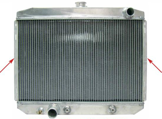
PHOTO 1: DOWN FLOW RADIATOR If your radiator looks like this, your side channels are here.
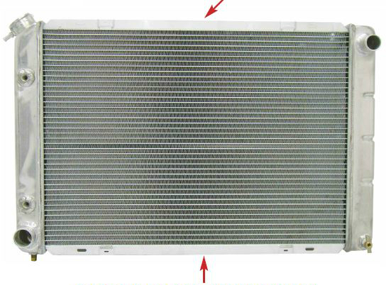
PHOTO 2: CROSS FLOW RADIATOR If your radiator looks like this, your side channels are here.
PLEASE NOTE: DO NOT mount your shroud to the radiator tanks, tubes, or the radiator core as this may damage your radiator. Any attempt to drill, rivet, or screw your fan shroud into a radiator tank or tube will cause the radiator to leak and become unusable.
NOTE: Most side channels fold out and away from the core as noted in PHOTO 1 AND 2. Some radiators have side channels which fold over the radiator core as noted in PHOTO 3.
If your side channel folds over the radiator core, extreme caution should be used when either drilling through the side channel of the radiator or permanently mounting the shroud to the radiator. Safety items like a “drill stop” may be necessary for this installation. If you are unable to drill through this “fold over” style channel, other mounting fabrication must be considered to mount the fan shroud to this type of radiator. We recommend you temporarily center the shroud on the radiator. Please note the location of the other engine mounted devices and drive belts as it’s necessary to find a location for the fan shroud which does not interfere with other components.
PLEASE NOTE: Your mark on the fan shroud will be critical for positioning and determines where to physically cut the actual fan opening as noted later in these instructions.
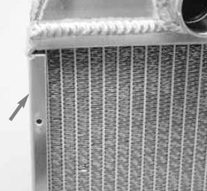
PHOTO 3: Folded over radiator side channel.
Step #2:
As you are temporarily determining the final mounting position of your shroud you will also want to note, measure and mark the center hub location of your engine’s fan as it relates to the fan shroud. See PHOTO 4.
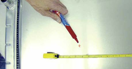
PHOTO 4: Mark fan center hub location.
Step #3:
When you are satisfied that you have the fan shroud and the “center fan hub” marked and positioned properly; equally space, measure and mark three (3) mounting holes on both outer side channel shroud flanges as shown in PHOTO 5.
Step #4:
Remove your temporarily mounted fan shroud from the radiator and then remove your radiator from the vehicle.
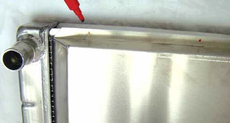
PHOTO 5: Marking outer flanges.
Step #5:
Determine the diameter & radius of your engines fan. Measure “tip to tip” from the outer edge of one fan blade to the outer edge of the opposing fan blade through the center hub of the fan. This is your diameter. The radius is ½ of the diameter (r = D/2). See PHOTO 6 as an example.
Step #6:
With your fan shroud removed from the radiator and laying engine side up on your work surface, drill a small hole through the center of your previously marked fan hub location as noted in PHOTO 4.
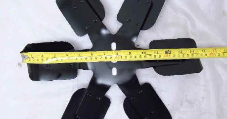
PHOTO 6: Measure your fan diameter.
Step #7:
Secure a string or wire the proper length through you previously drilled “hub hole” and with a scribe mark a total circle diameter (remember your string is the radius) 1 to 1.5” larger in diameter than the engine fan diameter. See PHOTO 7.
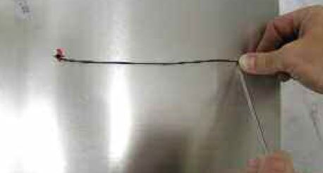
PHOTO 7: Measure and mark circle on fan shroud.
Step #8:
Carefully cut out your marked fan shroud opening. A jig saw, rotary tool or plasma cutter are some of the most common tools used to cut this opening. As necessary smooth the edge of the opening with a metal file or an appropriate sand paper. When completed, your opening should look similar to the fan shroud noted in PHOTO 8.
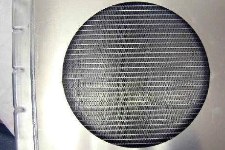
PHOTO 8: Fan Shroud Opening
Step #9:
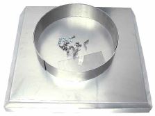
With the 3” x 65” fan ring, match the circumference of the hole to the appropriate length of the fan ring allowing for ends to have a 1” over lap. Secure and trim as necessary. See PHOTO 9.

PHOTO 9: Fan Ring
Step #10:
To the outside of the fan ring evenly space, mark, drill and secure the fan ring to the engine side of the fan shroud. Use all six of the 90º brackets with twelve of the stainless steel machine screws and lock nuts. See PHOTO 10 & 11.
NOTE - In some rare or uniquely fabricated applications the “Center Fan Hub” location could place a portion of the fan ring slightly above the shroud. In this instance, use the 3” x 7” flat tab provided to cut an arch shaped piece to fill the opening. Attach with tabs made from the extra fan ring material or TIG weld into place.
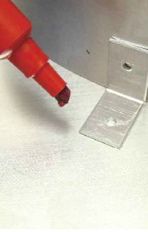
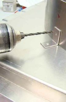
PHOTO 10: Marking 90º brackets.
PHOTO 11: Drilling 90º brackets.
Step #11:
Place your radiator engine side up on your work surface. Place and re-align your finished fan shroud in its final mounting position on your radiator. Drill and secure your fan shroud permanently to the side channels of the radiator based on your previous marking. (See PHOTO 12.) Use the remaining six (6) stainless steel machine screws and locking nuts or 6 self-tapping screws to secure your shroud to the radiator. Extending the range of the mounting flanges For radiators that are outside or inside the existing width of the shroud. Place the shroud and align it to the top of the radiator flange and mark the mounting hole positions on the top. (See PHOTO 13.) Using the provided L tab extensions, place the tabs in location on the bottom of the radiator flange and bridging to the shroud mark these locations. (See PHOTO 14 & 15.) Use the hardware included. Additionally a pop rivet or weld may be used.
NOTE - In some applications the flange or side channel will have limited or no access to the back side. In order to secure the shroud in these cases pop rivets or self tapping screws may offer the solution. Please remember EXTREME CAUTION should be exercised as outlined in Step #1.
Step #12:
Re-install your radiator and fan shroud (if able) as a complete assembly. Make sure you reconnect and replace ALL removed parts and hoses from your vehicle and refill your cooling system with the proper coolant.
PLEASE NOTE: Prior to starting your engine, make sure you check all of the moving engine components and engine fan for proper clearances from your new fan shroud assembly and adjust if and as necessary.
We offer a complete selection of cooling system plumbing, temperature control wiring, radiator mounting and modification products to complete your cooling system project. Please ask the location where you purchased this product for more details.
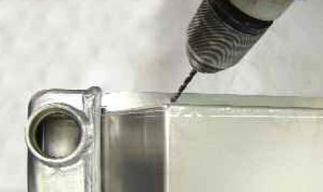
PHOTO 12: Drilling side channel.
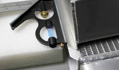
PHOTO 13: Align Radiator & Shroud.
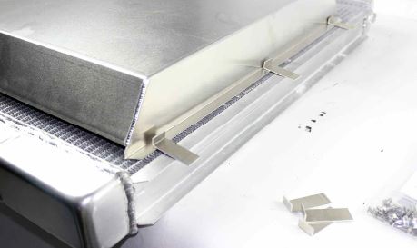
PHOTO 14: L Tab extensions.
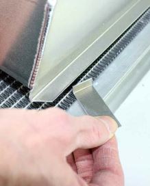
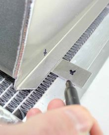
PHOTO 15: Insert & Mark location.